
Virtual Telepresence Robot
Redefine Reality and Experience the World
We aim to make a prototype of a virtual telepresence robot. This robot which is placed in a remote location is capable to capture the environment in virtual form using Raspberry Pi. The captured visuals are displayed on a webpage and virtual reality headset. The robot present in the remote location can be maneuvered by the user using their smartphone.
Introduction
Don't want to miss your kids birthday but can't cancel that important investors meeting? There's nothing to worry because
we have the perfect solution for you!
A Telepresence Robot is a videoconferencing bot that revolutionizes the way you feel. It enables people to be at
more than one place at a single time. It helps one feel more connected by giving a physical presence where one can't be in person.
Driving your own virtual presence robot means you are free to roam around the office, attend meetings, visit work sites, attend class a
and do much more from anywhere at anytime
We have implementing the following features in our virtual presence robot:
Design and Testing
The project was divided into various phases. We followed an incremental approach towards designing our telepresence robot. In this section, we'll be describing the design and testing approach we followed:
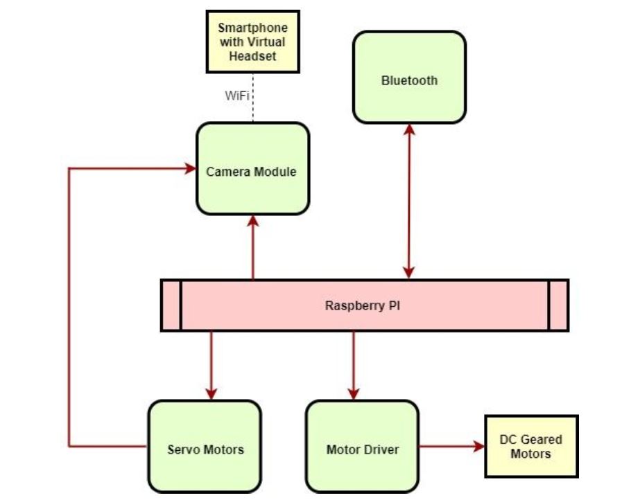
Initial Thought
At the nascent stages of the project, we had a fair picture of how our system should look like which was further improvised as we gained more undertsanding and got in depth with the project. The virtual presence robot which is present in the remote location should be able to move around the remote location controlled by commands sent on the smartphone communicating via Bluetooth. Parallely,it should record the video using the camera module which will be sent to the smartphone using WiFi. An additional feature is that the camera should move left and right based on the head movement of the user which is based on signals from the smartphone with magnetometer,accelerometer and gyroscope to the servo motors for controlling the camera.
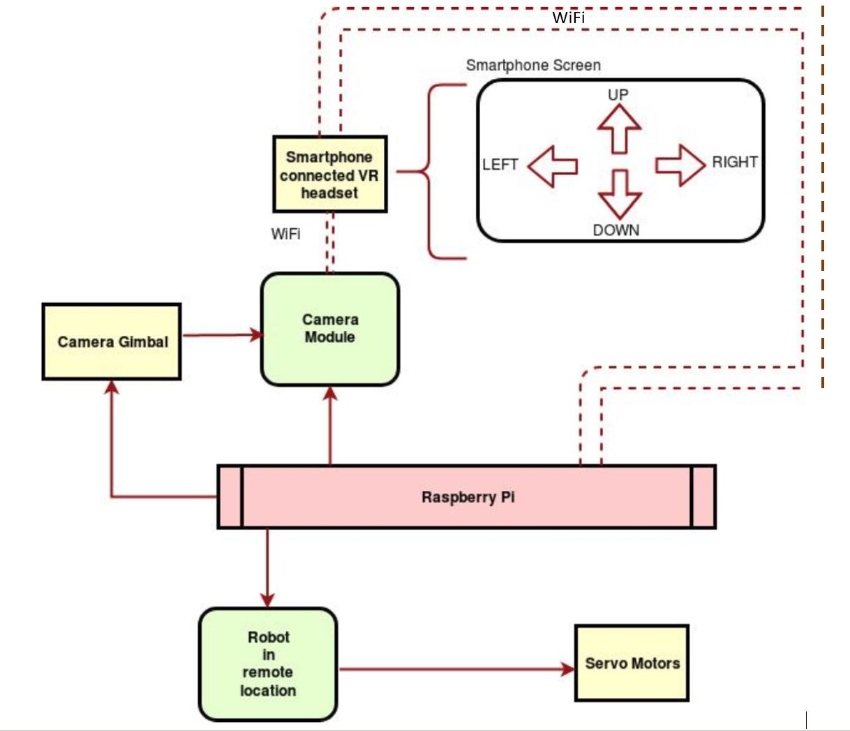
Final Block Diagram
As we moved ahead with finalizing our top level picture, we improvised on certain aspects and our final top level picture/block diagram looked like in the image below. Instead of using a Bluetooth Module, we control everything wirlessly using Wi-Fi. We combine the camera and servo motors to be replaced by a camera gimbal which is essentially the same thing built in a more sophisticated way. We decided to move ahead controlling the robot with servo motors and not DC motors to suit our application. To add to that, Servo motors are programmable and easy to work with.
Methodology
We followed a modular approach to design our virtual presence robot taking one part and developing the hardware and software for it and then testing it.In the end , we combined all the modules together and tied them at the top level.
DESIGN
The first step towards implementing the telepresence robot was to assemble a robot frame and to include Raspberry Pi and servo motors to make a mobile system. The mobile robot has three frames or levels to accommodate a camera mounted on a gimbal,Raspberry pi with connections to drive the gimbal and wheels of the robot and a battery source to supply power to Raspberry Pi.
TESTING
Next python script was written to control the movement of the servo meters by changing the duty
cycle of the PWM signal.
The left and right servos were controlled individually by passing the following signals:
Forward ----> Left Servo: Anticlockwise Direction , Right Servo: Clockwise Direction
Backward ----> Left Servo: Clockwise Direction , Right Servo: Anticlockwise Direction
Left ----> Left Servo: Stop , Right Servo: Anticlockwise Direction
Right ----> Left Servo: Clockwise Direction , Right Servo: Stop
The Duty Cycle is passed to an in-built function to change the direction of the motor. Duty cycle of 7.9 and 5.9 is given for anticlockwise
and clockwise rotation respectively.
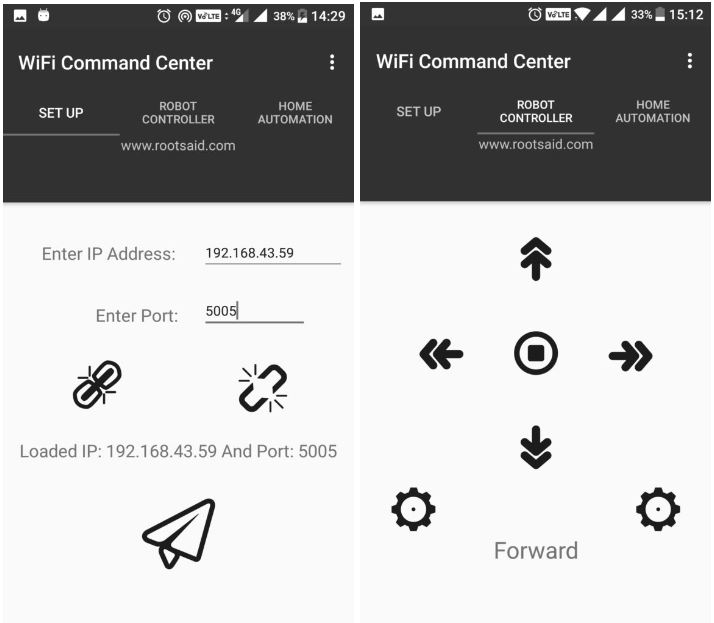
We then tested the Robot using WiFi Command Center App by RootSaid.
This app provides an interface to connect to a given port on a server and alsoprovides interface to send commands to the robot. The
following is a glimpse of the application:
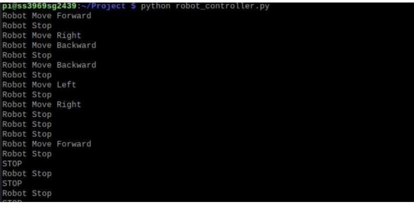
Lastly, this is combined with the script to control the servos of the system. The robot moves inthe direction chosen from the Wifi Command Center app. The output of this program can be seen on the terminal:
DESIGN
The first step towards this goal was to setup a PiCam and ensure that it captures images and
videos. The setup of the PiCam included:
- Setting up the Hardware by plugging in the camera module to the RPi Camera Port
- Adjusting the settings in Raspberry Configuration Tool by enabling the Camera Interface
- Reboot Raspberry Pi for the camera settings to work
TESTING
Next, we gave a test run of the Pi Camera from the terminal by running commands like raspistill or raspivid.
Using these commands, we made sure that the Pi Camera is working properly and images and videos are accurately captured
as it forms a major part of our system.
DESIGN
We decided to output the live screening from the camera onto a webpage. We followed the following procedure :
Apache is used to configure Raspberry Pi as server. It is readily available on the RPi to allow it to serve
web pages. Apache can serve HTML pages over Hyper Text Transfer Protocol (HTTP).
The following command is used to install apache:
sudo apt install apache2 -y
For our application, we need a webpage that is constantly changing that is everytime
it is viewd. For that purpose, we need to find a way to serve dynamic web pages.
With an additional PHP module, the RPi can also serve dynamic web pages.
sudo apt install php libapache2-mod-php -y
Using this , the apache server can process php files.
The next important step in our application is to stream in the video from the camera onto the system. For this purpose, For this we downloaded Web based interface for controlling the Raspberry Pi Camera, that includes motion detection, time lapse, and image and video recording. We clone the readily available RPi Cam Web Interface which contains three major files:
TESTING
- Installing apache on Raspberry Pi
- RPi camera web interface
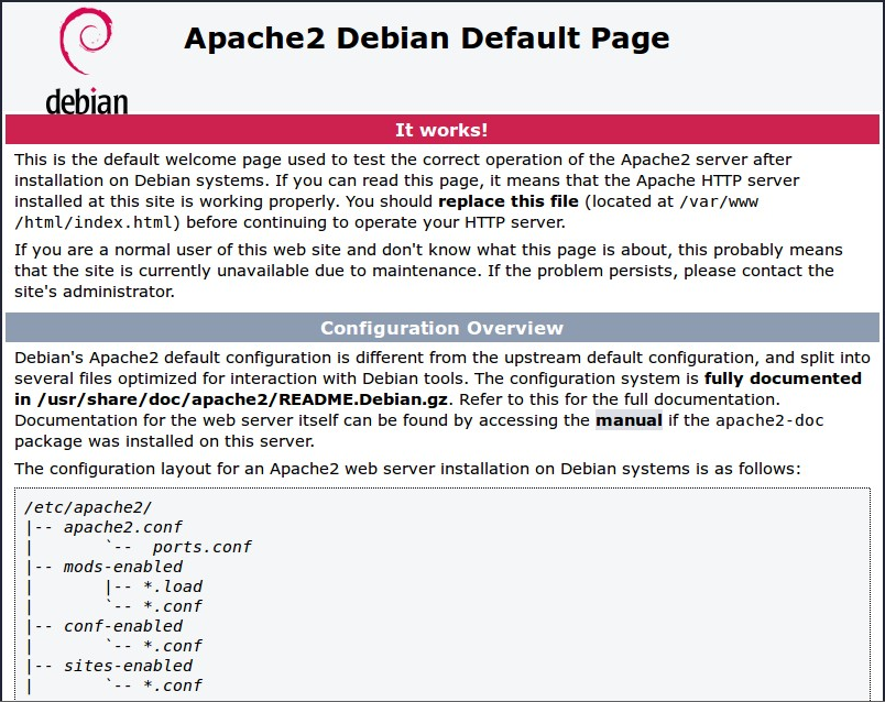
By default, Apache puts a test HTML file in the web folder. This default web page is served when you browse to whatever the Pi's IP address is from another computer on the network.After initial installation of apache2, the webpage is loaded as follows:
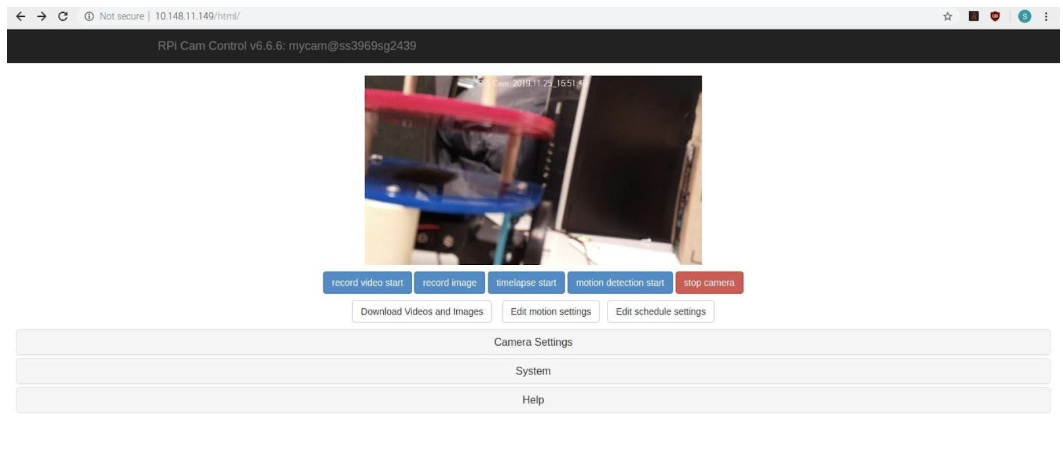
After installing the php files and RPi camera web interface, the dynamic web page looks like this on our IP address :
BACKGROUND
To map the real time response of the users head movement to the video captured by the camera, we make use of the inertial measurement unit which is in-built in smartphones and VR headsets nowadays. This helps is in avoiding an additional use of an IC and helps us in the direct transfer of data between the sender and reciever. Intertial Measurement Unit(IMU) is made of these three sensors:
Gyroscopes, however, measure angular velocity about three axes: pitch (x axis), roll (y axis) and yaw (z axis). When integrated with sensor fusion software, a gyro can be used to determine an object’s orientation within 3D space.
It measures linear acceleration (change of velocity) across a single axis. Integrating acceleration once reveals an estimate for velocity, and integrating again gives you an estimate for position.
A magnetometer, as the name suggests, measures magnetic fields. It can detect fluctuations in Earth’s magnetic field, by measuring the air’s magnetic flux density at the sensor’s point in space.
The data from these sensors can be used to map the users head position and can be used to send signals to the servo motors connected to the camera to rotate it.DESIGN
To mirror the rotation of the head of the user wearing the VR-headset, the data from the IMU must be used.
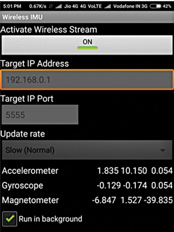
To utilise the readings from this sensor, an android app “Wireless IMU” is used.
This app sends the sensor readings to the target IP address and port via UDP as Comma Separated Values (CSV).
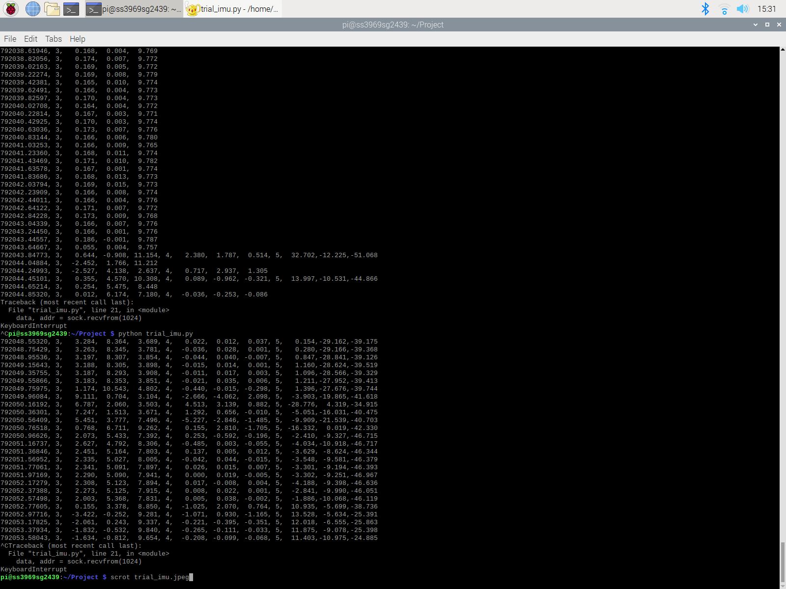
The UDP packet looks like:
Timestamp[sec], [Sensor ID(3)], x, y, z,[Sensor ID(4)], x, y, z,[Sensor ID(5)], x, y, z
where Sensor ID represents :
3: Accelerometer
4: Gyroscope
5: Magnetometer
This application can be run in the background to capture the data while one can watch the live screening.
We configured the application on the phone to run in the background connecting to the IP address and specific port.
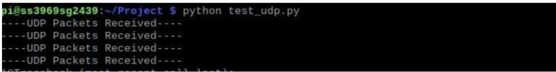
There was a test run done to capture the data sent by this application by using the socket function in python.
TESTING
The user interface of the application looks like this:
DESIGN
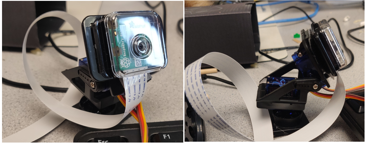
We used a camera gimbal which is made up of a slot for the Pi Camera and two servo motors,
one for the movement along X-axis and the other for the
movement along Y-axis. The X-axis movmement maps to the head movement in left-right direction and the Y-axis movement maps
to the head movement in top-down direction. A setup of the camera gimbal is shown below:
TESTING
The steps we followed during testing are :
- Initial Test: The gimbal lock consists of two servos which are controlled using Pulse Width Modulation using the RPi. We controlled the servos by passing duty cycle as an input to see how the servos repsond to the duty cycle values passed.
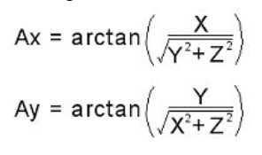
- In the next step, we combined the gimbal control and wirless imu application control. We picked up the data from the wirless imu application and using the accelerometer data, we calculated the angles. These angles were used to calculate the duty cycle which was passed to the changeDutyCycle function to change the duty cycle values of the servo motors. The data along X-axis is used to control the horizontal movement and the data along Y-axis is used to control the vertical movement. For the version one of the program, we took float values of the accelerometer data and used the GPIO library to control the servos. However, we faced some jittery movement of the gimbal which intrigued us to think deeper.
- To get rid of the jittery movement, we moved on from software PWM to hardware PWM using the pigpio library. pigpio is a wrapper for the pigpio C library to enable fast GPIO, PWM, servo control and state change. However, we observed that we got a smoother and more stable movement using the software PWM instead of the hardware PWM.
- At this stage, we moved back to controlling the servos using software PWM. This time, we converted the accelerometer from floating to integer values to stabilize the interger movement and form a more smoother callibration. The gimbal now captured crisper values and we were able to get rid of the jittery movement.
- FINAL DESIGN AND INTEGRATION
DESIGN
HARDWARE
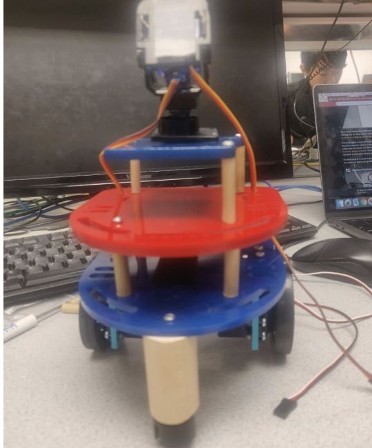
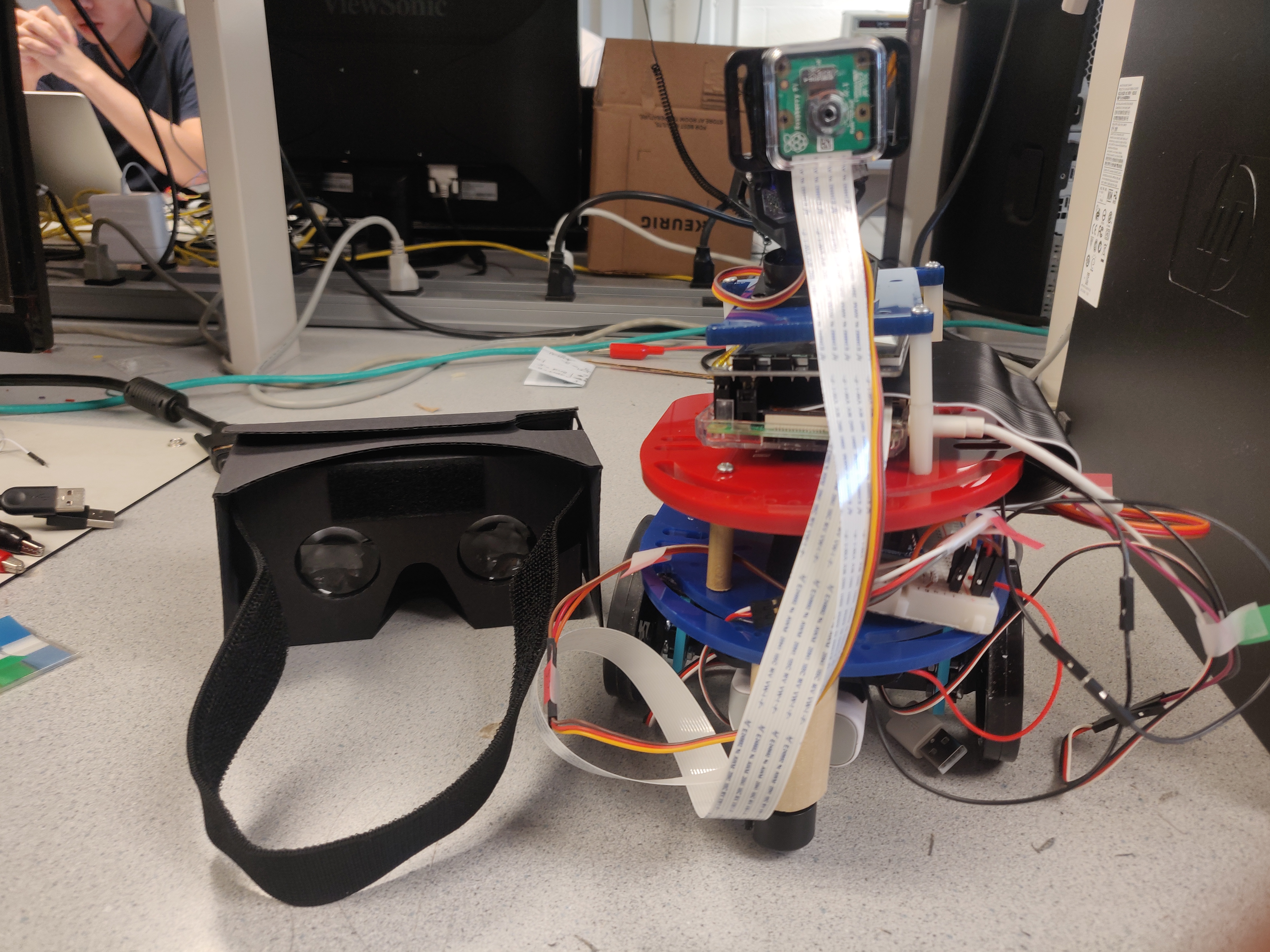
For our final design, we integrated all the components together and used a Google Cardboard VR headset to give a real time
experience to the user. Our final prototype looked like this:
SOFTWARE
For our final setup, we integrated all the python scripts to be run from a single bash script in the background. This bash
script ensures that all the processes are running concurrently. This helped us combine all the scripts smoothly.
In addition to this, we also added a special function to our robot control application where pressing one of the button kills
the currently running processes and transfers the control back to the user.
This is written in a bash file where the process ids are listed and used to kill the specific process which in our case can be
found out using the corresponding process name.
TESTING
We tested the final prototype by powering the RPi with a 5V power bank and powering the servos using a 6V battery pack.
A demo can be seen of the final working prototype:
Results
By the end of four weeks, the following goals were achieved:
Conclusions
After creating our own version of Virtual Telepresence Robot, we realized that this robot can enable
its users to remotely interact with and observe the people & their surrounding without being physically
present there themselves. These robots can change dynamics of countless domains: they can provide homecare
assistance to the elderly and even facilitate virtual attendance for physically challenged students. In
businesses, these robots can significantly reduce the need for traveling for meetings.
Thus, the virtual telepresence robot is a simple, cost-effective and efficient solution to multiple real world problems.
Future Work
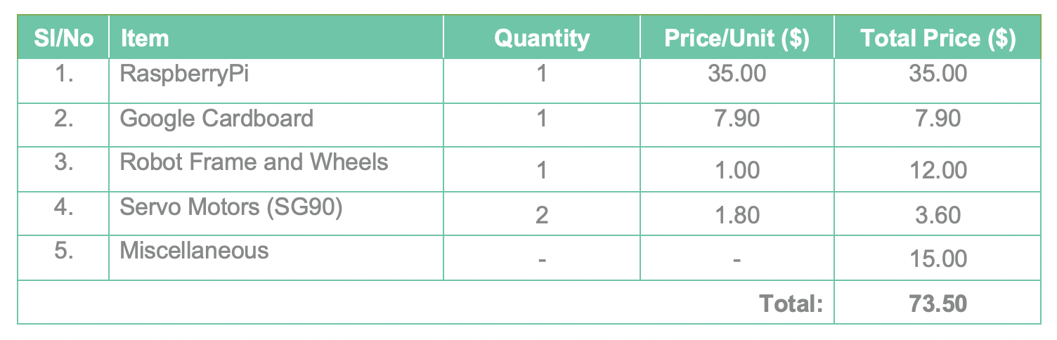
Budget
Code Appendix
The programs and source codes for this project can be on GitHub below:Meet The Team!

Shalki Srivastava
ss3969@cornell.edu

Shivangi Gambhir
sg2439@cornell.edu